Metallographic cutting—also called metallography sectioning or materialographic cutting—is the first physical step in metallographic sample preparation. Its purpose is to remove a small, representative specimen from a component, weld, coating, casting, forging, or failed part without introducing heat damage, deformation, edge chipping, or contamination.
A poor cut cannot always be corrected by grinding and polishing. Excessive heat may alter the microstructure near the cut surface; excessive force may create plastic deformation or microcracks; poor clamping may cause vibration, edge damage, or loss of a critical coating. For this reason, cutting is one of the most important stages in a metallographic laboratory.
This guide explains how to select the right metallographic cutting machine, cut-off wheel or diamond blade, coolant, clamping solution, and cutting parameters for reliable, low-deformation sectioning.
What Is Metallographic Cutting?
Metallographic cutting is the controlled removal of a representative sample from a larger component for subsequent metallographic examination and material testing.
The goal is not simply to separate a small piece from a larger part. The cut must preserve the material’s true condition and retain the features that will be examined later, such as:
-
Coating thickness and coating-substrate interface
-
Carburized or nitrided surface layer
-
Weld fusion zone and heat-affected zone
-
Casting porosity, shrinkage, or inclusions
-
Crack origin and fracture path
-
Grain structure and phase distribution
-
Heat-treatment condition
In a complete metallographic workflow, cutting is followed by mounting, grinding, polishing, etching, microscopy, hardness testing, and material analysis. Cutting quality directly affects how much damage must be removed during grinding and whether the final specimen can support reliable analysis.
For a broader explanation of the complete preparation sequence, see:
Complete Metallographic Sample Preparation Workflow: From Cutting to Material Analysis
What Is the Purpose of Metallographic Sectioning?
The purpose of metallographic sectioning is to obtain a specimen that accurately represents the material condition, manufacturing process, coating, weld, or failure feature being investigated.
A metallographic specimen may be taken from:
-
A gear tooth for case-depth and microstructure evaluation
-
A welded pipe for fusion, penetration, and heat-affected-zone inspection
-
A coated fastener for coating-thickness measurement
-
An aluminum casting for porosity and shrinkage analysis
-
A failed shaft for crack-origin and fracture-path investigation
-
A ceramic component for low-damage cross-sectioning
-
An electronic package for solder-joint or interface analysis
Why Is Proper Sectioning Important in Metallographic Sample Preparation?
Proper sectioning is important because damage created during cutting must be removed by subsequent grinding. If the damage layer is deep, the operator must remove more material, increasing preparation time and the risk of losing critical surface features.
Common cutting-induced problems include:
-
Thermal burns and heat tint
-
Recast layers or altered microstructure
-
Plastic deformation and smearing
-
Edge chipping and rounding
-
Microcracks in brittle materials
-
Delamination of coatings or plated layers
-
Incorrect sampling location
-
Excessive material loss
For coated parts, thin components, case-hardened steels, ceramics, and electronic packages, excessive sectioning damage can make the specimen unusable. A coating may be lost, a thin hardened layer may be removed, or a crack may be obscured by deformation.
What Features Must Sectioning Preserve?
| Feature | Sectioning Requirement |
|---|---|
| Coating or plating | Preserve thickness, interface, and edge |
| Carburized or nitrided layer | Retain surface layer and measure case depth |
| Weld | Preserve fusion line, heat-affected zone, and weld penetration |
| Casting defect | Retain porosity, shrinkage, or inclusion location |
| Fracture surface | Avoid damaging the crack origin or fracture morphology |
| Thin electronic package | Minimize kerf loss, heat, and mechanical stress |
| Ceramic or mineral sample | Prevent chipping, cracking, and thermal shock |
What Is the Difference Between Cutting and Sectioning?
Cutting and sectioning are related but not identical terms.
| Term | Meaning | Priority |
|---|---|---|
| Cutting | The general act of separating material | Speed, material removal, shape |
| Sectioning | Controlled removal of a representative specimen for examination | Specimen integrity, orientation, edge retention, low damage |
In metallography, sectioning must prioritize accuracy and specimen quality. A production cut may prioritize speed; a metallographic cut must preserve the features needed for microscopy, hardness testing, and failure analysis.
Sectioning is the first step in a complete metallographic workflow that continues through mounting, grinding, polishing, etching, microscopy, hardness testing, and material analysis. Learn how these stages work together in: What Is Metallography? Definition, Microstructure Analysis, Applications & Laboratory Guide
Abrasive Cutting vs. Precision Wafering
The two most common metallographic cutting methods are abrasive cutting and precision wafering. The correct choice depends on material hardness, toughness, thermal sensitivity, sample geometry, and the required analysis.
| Method | Best Applications | Advantages | Limitations |
|---|---|---|---|
| Abrasive cutting | Steel bars, castings, forgings, large components, routine QC | Fast, robust, high material-removal capacity | Greater risk of heat and deformation if parameters are wrong |
| Precision wafering | Hardened steel, ceramics, minerals, thin sections, electronics, high-value samples | Low kerf loss, precise cuts, reduced deformation | Lower throughput and higher consumable cost |
How Abrasive Cutting Works
Abrasive cutting uses a rotating cut-off wheel containing abrasive grains bonded in a resin, rubber, or resin-rubber matrix. The wheel removes material through controlled abrasion while coolant flushes the cutting zone.
Common abrasive types include:
-
Aluminum oxide: commonly used for ferrous metals and steels
-
Silicon carbide: commonly used for nonferrous metals, ceramics, and some nonmetallic materials
-
Diamond: used for ceramics, minerals, very hard materials, and precision sections
-
Cubic boron nitride (CBN): used for certain hard and tough ferrous alloys
Abrasive cut-off wheels typically contain aluminum oxide or silicon carbide particles bonded with a resin or rubber matrix. Aluminum oxide wheels are generally used for steels, while silicon carbide wheels are commonly selected for soft and medium-hard nonferrous metals as well as hard nonmetallic materials.
How Precision Wafering Works
Precision wafering uses a thin diamond or CBN blade to remove material with minimal kerf loss. It is preferred when deformation, heat input, and material loss must be minimized.
Precision wafering is commonly used for:
-
Ceramics and glass-ceramics
-
Minerals and geological samples
-
Sintered materials
-
Hard coatings
-
Thin metal sections
-
Electronic packages
-
Small or high-value specimens
Blade selection depends on abrasive type, grit size, concentration, bond type, blade thickness, and material hardness. Proper clamping is also essential to prevent specimen movement and vibration.
When to Use Wafer Cutting for Ceramics and Minerals
Use precision wafering when:
-
Material loss must be minimized
-
The sample is brittle and prone to chipping
-
The cut surface must remain flat and low-damage
-
The specimen is thin, small, or high-value
-
The material is a ceramic, mineral, glass-ceramic, or sintered component
For ceramics, resin-bonded diamond blades are commonly used for general ceramic work, while metal-bonded or electroplated diamond blades may be selected for harder or tougher grades. Continuous coolant flow is essential to prevent thermal shock.
Wet Cutting vs. Dry Cutting
Wet cutting is the preferred method for most metallographic sectioning because it controls heat, removes debris, and reduces the risk of thermal damage.
| Feature | Wet Abrasive Cutting | Dry Cutting |
|---|---|---|
| Heat control | Excellent | Limited |
| Swarf removal | Excellent | Limited |
| Risk of burn | Lower | Higher |
| Wheel loading | Lower | Higher |
| Typical application | Most metallographic samples | Special materials or specific processes |
Coolant flushes the wheel, removes debris from the cutting area, and reduces frictional heat. Insufficient coolant can cause burn marks, microstructural alteration, and premature wheel wear.
Dry cutting may be necessary for certain materials or processes, but it requires greater attention to feed rate, wheel condition, and heat generation.
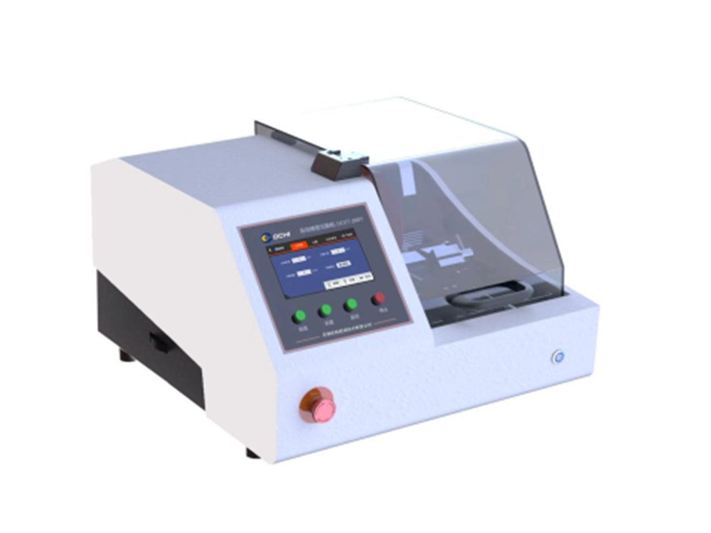
What Is a Metallographic Cutting Machine?
A metallographic cutting machine is a laboratory machine designed to section specimens with controlled speed, feed, cooling, and clamping to minimize heat and deformation.
A typical machine includes:
-
Cutting motor and spindle
-
Cut-off wheel or precision saw blade
-
Specimen clamping system
-
Coolant reservoir and recirculation system
-
Manual or automatic feed mechanism
-
Enclosure and safety interlocks
-
Control panel for speed, feed rate, and cutting mode
The machine, clamping tools, cut-off wheel, coolant, cutting mode, feed speed, and rotational speed all influence the final cut quality.

Manual vs. Automatic Metallographic Cutting Machine
| Feature | Manual Cutting Machine | Automatic Cutting Machine |
|---|---|---|
| Feed control | Operator-dependent | Programmable and repeatable |
| Throughput | Lower | Higher |
| Repeatability | Depends on operator skill | More consistent |
| Best use | Low volume, varied samples, method development | Routine QC, batch sampling, production labs |
| Typical risk | Inconsistent feed and pressure | Higher initial investment |
Manual machines are suitable for low-volume laboratories, unusual samples, and method development. Automatic machines are preferred when laboratories need repeatable feed rate, consistent cooling, and higher sample throughput.
Automatic machines can reduce operator-induced variation, especially for brittle materials where inconsistent feed may cause cracks or edge damage.
How to Choose a Metallographic Cutting Machine
Key Machine Selection Criteria
When selecting a metallographic cutting machine, consider:
-
Maximum workpiece size and weight
-
Wheel or blade diameter
-
Cutting capacity and kerf loss
-
Motor power and speed range
-
Manual, semi-automatic, or automatic feed
-
Coolant-tank capacity and filtration
-
Clamping options
-
Enclosure size and safety features
-
Noise and vibration reduction
-
Ease of cleaning and maintenance
Manual, Semi-Automatic, or Fully Automatic?
| Laboratory Type | Recommended Configuration | Main Benefit |
|---|---|---|
| University or R&D laboratory | Manual precision saw or abrasive cutter | Flexibility for varied materials |
| Small QC laboratory | Manual or semi-automatic cutter | Lower investment with dependable routine capability |
| Production QC laboratory | Automatic abrasive cutter | Higher throughput and repeatability |
| Failure-analysis laboratory | Precision wafering saw | Low-damage sectioning of critical samples |
| High-volume automotive or metals laboratory | Automatic cutter with programmable parameters | Consistency, traceability, and capacity |
Feed Rate Control in Automatic Cutting Machines
Feed rate controls how quickly the wheel or blade advances into the specimen. It must balance cutting efficiency against heat generation and mechanical damage.
-
Too high a feed rate increases frictional heat and the risk of thermal burns.
-
Too low a feed rate prolongs cutting and may increase wheel loading.
-
Material-specific feed rates are commonly below 1.0 mm/s, but the correct value depends on the wheel, material, and machine.
-
Automatic machines can maintain a controlled feed rate and reduce operator variation.
Noise and Vibration Reduction Features
Vibration can cause edge chipping, poor surface finish, inaccurate cuts, and premature wheel wear.
Look for:
-
Rigid machine frame and stable base
-
Effective specimen clamping
-
Balanced spindle and wheel system
-
Vibration-damping features
-
Proper wheel alignment
-
Adequate coolant delivery
-
Enclosure design that reduces noise and contains coolant mist
Understanding Metallographic Cutting Consumables
Cutting consumables include cut-off wheels, diamond blades, CBN blades, coolants, clamping accessories, and cleaning materials. They must be selected as part of a complete cutting method, not as isolated purchases.
| Consumable | Main Function | Selection Factor |
|---|---|---|
| Abrasive cut-off wheel | Removes material by abrasion | Material hardness, toughness, and heat sensitivity |
| Diamond wafering blade | Precision sectioning with low kerf loss | Brittle, hard, or high-value materials |
| CBN blade | Precision cutting of ferrous materials | Hardened steels and ferrous alloys |
| Coolant | Controls heat and removes swarf | Material compatibility and corrosion protection |
| Clamping fixture | Stabilizes specimen | Geometry, fragility, and orientation |
| Cleaning solution | Removes residue after cutting | Material and coolant compatibility |
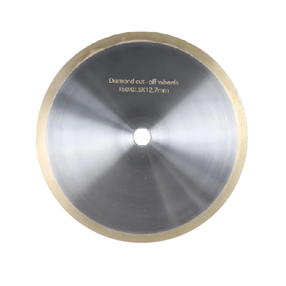
How to Choose the Right Cut-Off Wheel
The correct cut-off wheel depends on the material’s hardness, toughness, thermal sensitivity, and the required cut quality.
Abrasive Types
| Abrasive | Typical Application | Key Benefit |
|---|---|---|
| Aluminum oxide | Ferrous metals and steels | Effective for many ferrous alloys |
| Silicon carbide | Nonferrous alloys, ceramics, and some nonmetals | Suitable for nonferrous and hard brittle materials |
| Diamond | Ceramics, minerals, very hard materials, precision sections | Low kerf loss and high precision |
| CBN | Hardened ferrous materials | Effective for certain hardened steels |
Aluminum oxide wheels are generally used for steels. Silicon carbide wheels are commonly selected for soft and medium-hard nonferrous metals, glass, stone, and other hard nonmetallic materials. Diamond wheels are used for hard ceramics, ceramic composites, and geological materials, while CBN wheels are used for tough cobalt- and nickel-based alloys, hard metals, hard composite materials, and hard-to-very-hard carbon steels.qatm+2
Bond Types: Resin vs. Resin-Rubber
| Bond Type | Typical Use | Characteristics |
|---|---|---|
| Resin bond | General-purpose metallographic cutting | Consistent cutting action, suitable for many metals |
| Resin-rubber bond | Softer or more heat-sensitive materials | More compliant cutting action, reduced risk of burning |
| Metal bond | Hard ceramics and demanding precision applications | Durable and suitable for certain diamond blades |
Bond hardness affects how quickly worn abrasive grains break away and expose fresh cutting grains.
-
Hard materials generally require a soft bond.
-
Medium-hard materials generally require a medium-hard bond.
-
Soft materials generally require a hard bond.qatm+1
Abrasive Grain Size and Concentration
Coarser abrasives remove material faster but may create a rougher surface. Finer abrasives produce a smoother cut but may cut more slowly.
| Grain Size | Cutting Speed | Surface Finish | Typical Use |
|---|---|---|---|
| Coarse | Faster | Rougher | Fast cuts in low-hardness materials |
| Medium | Balanced | Moderate finish | General-purpose sectioning |
| Fine | Slower | Smoother | Hard materials and precision cuts |
Fine-grained wheels are excellent for precise and smooth cuts in higher-hardness materials, while coarse-grained wheels are better for fast, efficient cuts in low-hardness materials.
How to Select a Diamond or CBN Blade
| Blade Type | Best Applications | Selection Consideration |
|---|---|---|
| Diamond blade | Ceramics, minerals, glass, sintered materials, hard coatings | Abrasive size, concentration, bond, and blade thickness |
| CBN blade | Hardened ferrous materials | Suitable for certain hardened steels and ferrous alloys |
Use thinner blades when kerf loss and heat input must be minimized. Use appropriate grit and concentration for the material’s hardness and brittleness. Ensure the blade is compatible with the machine spindle, speed range, and coolant system.
Why Is Coolant Critical in Metallographic Cutting?
Coolant controls frictional heat, removes swarf, protects the specimen from thermal damage, and helps maintain cutting efficiency.
Coolant flushes the wheel and removes debris from the cutting area. Insufficient coolant can cause burn marks, microstructural alteration, and premature wheel wear.
Coolant should provide lubrication and corrosion protection, especially for ferrous samples. Flow should be directed precisely into the cutting zone.
Choosing the Best Coolant for Metallographic Sectioning
| Material Group | Coolant Consideration | Recommended Approach |
|---|---|---|
| Carbon and alloy steels | Heat and corrosion control | Use compatible water-based coolant with corrosion protection |
| Stainless steel | Heat control and surface protection | Maintain consistent flow and avoid contamination |
| Aluminum alloys | Swarf removal and surface protection | Use compatible coolant and avoid excessive pressure |
| Titanium alloys | Heat control | Use ample coolant and controlled feed |
| Coated samples | Coating preservation | Ensure coolant reaches the cutting interface |
| Ceramics and minerals | Crack prevention | Use precision wafering and stable coolant delivery |
For ceramics, continuous and copious coolant flow is essential to prevent thermal shock. Water-based cutting fluid is commonly preferred for ceramic sectioning.
Choosing the Right Clamping Solution
Clamping must hold the specimen securely without introducing stress, movement, vibration, or damage to the region of interest.
| Specimen Type | Clamping Consideration | Recommended Approach |
|---|---|---|
| Regular metal block | Stable support | Standard vise or clamp |
| Thin sheet | Prevent bending and vibration | Backing plate and low-stress clamping |
| Coated sample | Prevent delamination | Support coating against a backing material |
| Small specimen | Prevent movement | Precision fixture or mounting |
| Brittle material | Prevent cracking | Low-stress clamping and precision saw |
| Irregular component | Maintain orientation | Custom fixture or support block |
For coated specimens, clamp the coated surface against a backing material to reduce delamination and edge chipping.
Cutting Speed, Feed Rate and Force
The key cutting parameters are cutting speed, feed rate or pressure, and cooling.
| Parameter | Too High | Too Low | Engineering Approach |
|---|---|---|---|
| Cutting speed | Heat, burns, wheel wear | Inefficient cutting | Match speed to wheel and material |
| Feed rate | Thermal damage, deformation | Long cutting time, wheel loading | Use controlled feed and monitor load |
| Force | Deformation, cracking, burns | Slow removal | Let the abrasive cut; avoid forcing the wheel |
For ceramics, blade speed itself rarely causes chipping; feed rate and lateral support are more important. Thin, fragile, or thermal-shock-sensitive samples require slower, steadier feed and strong support.
How to Make a Proper Metallographic Cut
Step 1: Prepare the Work Area and Equipment
-
Confirm the analysis objective and required sampling location.
-
Inspect the machine, wheel or blade, coolant level, and clamping tools.
-
Select the correct consumables for the material.
-
Ensure guards, interlocks, and coolant delivery are functioning.
Step 2: Secure the Sample Properly
-
Mark the required cutting location and orientation.
-
Support thin, fragile, or coated samples with a backing material.
-
Clamp securely without overstressing the specimen.
-
Confirm that the specimen cannot move during cutting.
Step 3: Adjust Cutting Parameters
-
Select the appropriate wheel or blade.
-
Set the recommended rotational speed.
-
Set a controlled feed rate.
-
Confirm coolant flow is directed into the cutting zone.
Step 4: Start Cutting with a Steady Motion
-
Begin cutting smoothly; avoid forcing the wheel into the specimen.
-
Maintain consistent feed and avoid sudden pressure changes.
-
For manual cutting, use steady, controlled movement.
-
For automatic cutting, monitor machine load and feed behavior.
Step 5: Monitor Cooling and Lubrication
-
Confirm continuous coolant coverage at the cutting interface.
-
Watch for coolant starvation, wheel loading, vibration, or burn discoloration.
-
Stop and correct the process if heat damage or unstable cutting occurs.
Step 6: Inspect the Cut Quality
After cutting, inspect the specimen for:
-
Burn marks or heat tint
-
Edge chipping
-
Cracks
-
Deformation
-
Coating delamination
-
Excessive kerf loss
-
Incorrect sampling location
-
Contamination
If damage is present, adjust wheel selection, feed rate, coolant flow, clamping, or cutting method before preparing the next specimen.
Material-Specific Cutting Guidelines
Cutting Carbon and Alloy Steels
Use appropriate aluminum oxide abrasive wheels for many ferrous alloys. Maintain adequate coolant and controlled feed. For hardened steels, reduce heat input and consider precision sectioning.
Optimizing Cutting Parameters for Titanium Alloys
Titanium is heat-sensitive and requires controlled cutting conditions. Use ample coolant, controlled feed, and a wheel or blade matched to titanium. Avoid excessive pressure, which can increase heat and deformation.
Best Coolant Practice for Stainless Steel Sectioning
Maintain consistent coolant flow at the cutting zone. Use a coolant compatible with stainless steel and equipment materials. Prevent coolant contamination and monitor corrosion protection.
Low-Deformation Sectioning of High-Hardness Steels
Use a sharp, appropriate abrasive wheel or precision saw. Reduce feed rate and avoid forcing the cut. Ensure stable clamping and sufficient coolant. Consider precision wafering for critical microstructural evaluation.
Cutting Aluminum Alloys
Aluminum is soft and prone to smearing and deformation. Use low pressure, effective swarf removal, and appropriate coolant. Avoid overly aggressive wheels or excessive feed.
Cutting Coated Samples Without Delamination
Cut perpendicular to the coating surface when coating thickness must be measured. Use precision wafering with a diamond blade for thin or sensitive coatings. Support the coated surface with a backing material, use a low feed rate, and ensure adequate coolant.
Preventing Micro-Cracks in Brittle Materials
Use precision wafering with a diamond blade. Reduce load and feed rate. Use stable clamping to prevent vibration. Avoid thermal shock and ensure adequate coolant.
Common Issues in Metallographic Sample Cutting
Why Does My Sample Show Burn Marks or Overheating?
Common causes include:
-
Feed rate too high
-
Insufficient coolant flow
-
Incorrect wheel selection
-
Dull or loaded wheel
-
Excessive cutting pressure
Reduce feed rate, improve coolant delivery, replace or dress the wheel, and verify wheel-material compatibility.
Why Does My Coated Sample Delaminate?
Common causes include:
-
Wrong cutting direction
-
Excessive heat
-
Poor clamping support
-
Excessive vibration
-
Incorrect blade or wheel
Cut from coating into substrate, support the coated surface, reduce feed, and use precision wafering when necessary.
Why Does My Brittle Sample Chip or Crack?
Common causes include:
-
Excessive load
-
Vibration
-
Incorrect blade
-
Thermal shock
-
Poor clamping
Use precision wafering, reduce feed, improve clamping, and maintain stable coolant delivery.
Why Is My Cut Surface Rough or Deformed?
Common causes include:
-
Worn wheel
-
Excessive feed
-
Insufficient coolant
-
Machine vibration
-
Incorrect abrasive or bond type
Replace or dress the wheel, reduce feed, improve coolant flow, and verify machine stability.
What Is the Difference Between Burning and Deformation?
| Issue | Cause | Effect |
|---|---|---|
| Burning | Excessive frictional heat | Altered microstructure, heat tint, possible hardness change |
| Deformation | Excessive mechanical force | Distorted grains, smearing, residual stress |
Both can compromise metallographic interpretation and must be prevented through correct parameters and consumables.
Post-Cutting Sample Handling and Preparation
After cutting, handle the specimen carefully to preserve the cut surface and prevent contamination.
-
Rinse the specimen to remove swarf and coolant residue.
-
Dry the specimen promptly to prevent corrosion.
-
Label the specimen with a unique identification number.
-
Record sampling location, orientation, material grade, and batch information.
-
Inspect the cut surface before mounting or grinding.
-
Store specimens in a clean, dry container if preparation will be delayed.
Cost Analysis Before and After Purchasing a Metallographic Cutting Machine
The true cost of a cutting machine includes equipment, consumables, labor, rework, downtime, and the cost of incorrect quality decisions.
| Cost Factor | Manual / Outsourced Preparation | In-House Metallographic Cutting |
|---|---|---|
| Equipment investment | Lower initial cost | Higher initial investment |
| Labor | May require external laboratory time | Requires trained internal operator |
| Turnaround time | Often longer | Faster for routine samples |
| Repeatability | Depends on provider or operator | Can be standardized with SOPs |
| Sample confidentiality | May require sending parts externally | Controlled internally |
| Rework risk | Depends on external method control | Can be reduced through controlled parameters |
| Long-term cost per specimen | Can become high with volume | Often lower at sufficient sample volume |
A cutting machine becomes most valuable when a laboratory needs repeatable sectioning, rapid turnaround, controlled parameters, and traceable sample preparation.
Metallographic Cutting FAQ
What Is the Purpose of Metallographic Cutting?
Metallographic cutting removes a representative specimen from a larger component while preserving the microstructure, coatings, welds, and features needed for analysis.
What Is the Difference Between Abrasive Cutting and Precision Wafering?
Abrasive cutting is faster and suitable for many routine metal samples. Precision wafering uses thin diamond or CBN blades for low-damage, low-kerf-loss sectioning of hard, brittle, thin, or high-value samples.
What Is the Best Coolant for Metallographic Cutting?
The best coolant depends on the material and machine, but it should control heat, remove swarf, provide lubrication, and protect against corrosion.
Can Metallographic Cutting Be Used on Ceramics?
Yes. Ceramics, minerals, sintered materials, and other hard, brittle materials are commonly sectioned using precision wafering with diamond blades.
Does Metallographic Cutting Require Coolant?
For most metallographic applications, yes. Coolant controls heat, removes debris, reduces wheel loading, and helps prevent thermal damage.
How Do I Prevent Burn Marks During Cutting?
Use a suitable wheel or blade, reduce feed rate, ensure adequate coolant flow, avoid excessive pressure, and replace worn consumables.
How Do I Prevent Coating Delamination?
Cut from the coating into the substrate, support the coated surface, reduce feed rate, use precision wafering where appropriate, and ensure adequate coolant.
How to Build a Reliable Metallographic Cutting Workflow
Reliable cutting is achieved by matching the machine, wheel or blade, coolant, clamping solution, and cutting parameters to the material and analysis objective.
-
Define the analysis objective before cutting.
-
Select the correct cutting method: abrasive cutting or precision wafering.
-
Match the wheel or blade to material hardness, toughness, and thermal sensitivity.
-
Use stable clamping and adequate coolant.
-
Control feed rate, speed, and pressure.
-
Inspect every cut for burns, cracks, chips, deformation, and delamination.
-
Document cutting parameters and consumables for traceability.
Choose the Right Metallographic Cutting Solution
For routine QC, prioritize fast abrasive cutting with repeatable feed and reliable cooling. For failure analysis, prioritize precision wafering, low deformation, and edge retention. For coated samples, prioritize perpendicular sectioning, backing support, and fine diamond blades. For ceramics and minerals, prioritize diamond wafering blades and low-load cutting. For high-volume laboratories, prioritize automatic feed, programmable parameters, and coolant management.
Need help selecting the right metallographic cutting machine, cut-off wheel, diamond blade, coolant, or clamping solution for your materials? Contact our application team for a tailored metallographic sectioning solution.