Metallographic grinding removes sectioning damage and establishes a flat examination surface before polishing. The best grinding method is not the coarsest abrasive or the longest sequence. It is the shortest validated process that removes damage while preserving the specimen’s edges, phases, and target features.
That distinction matters when a laboratory is preparing thin coatings, aluminum alloys, hardened steels, porous castings, or expensive failure-analysis specimens. A method that removes material quickly may also erase the region of interest, embed abrasive particles, or leave deformation that becomes apparent only after polishing.
Reliable results come from matching four elements: the specimen, the abrasive system, the machine controls, and the inspection endpoint. Grinding papers and discs cannot be selected independently of the mounting arrangement, force application, fluid conditions, and final analysis.
This guide explains how to build a metallographic grinding process, troubleshoot preparation artifacts, compare grinding consumables, and select a metallographic grinding and polishing machine using evidence from representative specimens.
What Is Metallographic Grinding—and What Should It Achieve?
Metallographic grinding is an abrasive preparation process used to expose and flatten a specimen surface while progressively removing damage from sectioning and preceding preparation steps.
It differs from production grinding because the objective is not to manufacture a functional component. The objective is to prepare a representative surface from which material structure and condition can be evaluated. Metallographic examination ultimately aims to reveal the constituents and structure of metals and alloys; preparation must support that objective rather than obscure it.
What Is the Purpose of Grinding in Metallography?
Grinding has three principal functions:
-
Remove sectioning damage and surface irregularities.
-
Establish the required examination plane.
-
Reduce the damage left by each abrasive step to a level that subsequent preparation can remove efficiently.
Every grinding step also introduces some damage of its own. Progressively finer abrasives reduce that damage, but usually remove material more slowly. The sequence must therefore balance removal rate against the depth and character of the remaining damage.
What Makes Metallographic Grinding Different from Production Grinding?
| Factor | Production grinding | Metallographic grinding |
|---|---|---|
| Primary objective | Meet component geometry and finish requirements | Prepare a representative examination surface |
| Workpiece | Functional component | Laboratory specimen |
| Main concern | Manufacturing specification and output | Preserve evidence while removing preparation damage |
| Completion criterion | Drawing and process requirements | Flatness, damage removal, and readiness for further preparation |
| Consequence of excessive removal | Dimensional nonconformance | Loss of a coating, defect, interface, or target plane |
A bench grinder or general mechanical grinder should not be treated as an equivalent substitute for a controlled metallographic preparation system simply because both remove metal.
Grinding vs. Polishing: Where Does One End and the Other Begin?
Grinding primarily establishes the plane and removes preceding damage. Polishing continues the refinement process, removing grinding deformation and reducing scratches to the level required by the analysis.
There is no single abrasive-size boundary that defines the transition for every material. Diamond can be used on a fixed grinding disc, on a fine-grinding surface, or with a polishing cloth. The supporting surface and material-removal mechanism matter as much as the abrasive name.
For that reason, a method should identify the complete abrasive–surface combination, not merely state “9 µm diamond.”
What Does an Acceptable Ground Surface Look Like?
An acceptable surface should meet the requirements of the next operation:
-
The intended examination region is exposed.
-
The surface is sufficiently flat.
-
Deeper scratches from earlier stages have been removed.
-
There is no unacceptable edge loss, smearing, or pull-out.
-
The remaining surface condition can be refined efficiently during polishing.
A bright appearance is not an acceptance criterion. Intermediate preparation stages can retain visible scratches while successfully reducing deformation.
Before Grinding: Check the Cut, Mount, and Examination Target
Grinding problems frequently begin before the specimen reaches the platen.
A severely damaged cut, an unsupported coating edge, or a specimen mounted at the wrong orientation cannot be solved reliably by extending grinding time.
How Sectioning Damage Determines the Starting Abrasive
Start by inspecting the cut surface and reviewing how it was produced.
A specimen sectioned with a suitable metallographic saw may require less initial stock removal than a specimen taken using an uncontrolled cutting method. Starting unnecessarily coarse creates additional damage that later stages must remove.
Published preparation guidance recommends starting with the finest abrasive capable of establishing a flat surface and removing sectioning effects efficiently. As an example, ANSI/CAMI 180–240, approximately P180–P280, is often sufficient for specimens appropriately sectioned with a metallographic abrasive saw; softer materials may justify a finer start. These are starting references, not universal recipes.
If heavy grinding is repeatedly required, review the cutting process before increasing grinding capacity.
If specimens repeatedly require heavy grinding to remove burns or deformation, review the sectioning process before adding more grinding steps. Our guide to low-damage metallographic cutting explains how machine settings, cutting wheels, coolant, and clamping affect the surface delivered to grinding.
How Mounting and Clamping Affect Flatness and Edge Retention
Check whether the mount fits the holder correctly, the specimen is stable, and the target edge is supported.
A specimen that rocks during preparation may develop a tapered surface. A gap between the specimen and resin may leave a coating edge insufficiently supported. Changing abrasive paper without correcting these conditions can repeat the same failure.
Before changing the grinding abrasive, check whether the specimen is adequately supported. Our guide to metallographic mounting methods and edge retention explains how resin selection, shrinkage gaps, and mounting conditions can affect the prepared edge.
Define the Material-Removal Limit Before You Start
Routine specimens may tolerate substantial stock removal. Targeted cross-sections often do not.
Before grinding a miniature assembly, narrow defect, or thin layer, define:
-
The target plane.
-
The approximate distance to that plane.
-
How position will be checked.
-
Inspection intervals.
-
Conditions requiring the process to stop.
A practical method card should answer: “How will the operator know that the required region has been reached?” A timer alone cannot answer that question.
Set the Preparation Endpoint Around the Final Analysis
| Final analysis | Grinding requirement to prioritize |
|---|---|
| Routine optical microscopy | Consistent input for polishing and microstructural observation |
| Coating-thickness measurement | Edge support and preservation of the original interface |
| Microhardness testing | Flatness and removal of preparation-induced damage |
| SEM or EBSD | Controlled input to subsequent fine preparation |
| Targeted cross-sectioning | Position control and limited material removal |
Grinding does not complete every preparation requirement. For example, EBSD generally requires subsequent preparation that removes residual surface deformation; the grinding endpoint should be defined as part of that complete method.
How Metallographic Grinding Works: Abrasives, Contact and Surface Damage
Abrasive particles interact with the specimen surface under load and relative motion. Useful cutting removes material, but unfavorable contact conditions can also deform, smear, fracture, or dislodge features.
Material Removal vs. Plastic Deformation
A high apparent removal rate is not automatically a good result.
In a ductile material, an unsuitable abrasive–surface–load combination can spread material across pores or phase boundaries. In a brittle constituent, aggressive contact can cause fragmentation or pull-out.
High force, insufficient lubrication, inappropriate abrasives, and poor process control can increase preparation-induced deformation.
The engineering objective is controlled removal—not simply maximum removal.
Why Flatness, Roughness and Subsurface Damage Are Different
These terms describe separate properties:
| Property | Meaning | Why it matters |
|---|---|---|
| Flatness | Overall conformity to the intended plane | Supports focus, geometry, and measurement |
| Roughness | Small-scale surface texture | Affects subsequent refinement and visibility |
| Subsurface damage | Altered material beneath the surface | Can influence etching and interpretation |
A specimen can look smooth yet retain deformation. It can also have fine scratches while remaining non-flat.
This explains why a surface that appears satisfactory under low magnification may reveal problems after etching or final polishing. The preparation sequence must remove damage, not merely improve appearance.
How Grinding Artifacts Affect Metallographic Interpretation
Common artifacts include:
-
Smearing that covers structural detail.
-
Embedded abrasive particles that resemble material constituents.
-
Pull-out that resembles genuine porosity.
-
Relief between hard and soft phases.
-
Rounded edges that compromise layer measurement.
-
Deep scratches that interfere with imaging and measurement.
These artifacts can arise from contamination, material characteristics, abrasive selection, and inappropriate preparation conditions.
Preparation artifacts matter because they can be mistaken for features of the material itself. For the wider analytical context, read our introduction to metallography and microstructure analysis, which explains how prepared specimens support quality control, process verification, and failure investigation.
How to Select Grinding Papers, Discs and Abrasive Surfaces
Select a consumable system against the specimen and required outcome, not only its unit price or nominal grit.
When to Use Silicon Carbide Grinding Papers
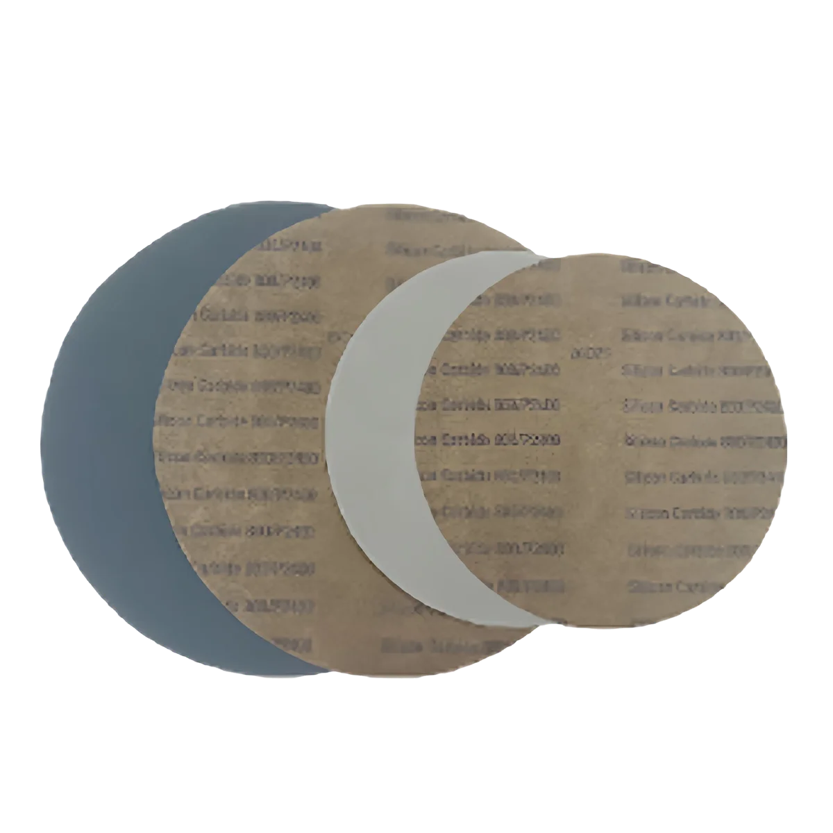
SiC grinding papers are widely used in metallographic preparation. They provide a straightforward way to change abrasive size and replace a worn or contaminated surface.
Evaluate:
-
Material compatibility.
-
Cutting efficiency throughout usable life.
-
Loading and debris accumulation.
-
Scratch consistency.
-
Backing and mounting method.
-
Fluid compatibility.
For very soft metals, finer SiC particles can embed in the specimen. Published guidance specifically identifies this risk in materials such as lead, tin, cadmium, and bismuth. Do not assume that a paper suitable for steel is equally suitable for every soft-metal system.
When selecting metallographic grinding papers, check the abrasive grading standard, disc diameter, and backing system against your current method and platen. A grit number alone is not enough to confirm that a replacement paper is equivalent.
When to Consider Fixed Diamond Grinding Discs
Fixed diamond discs are worth evaluating for hard materials, including ceramics and sintered carbides, and for applications needing controlled stock removal.
Published guidance gives diamond sizes of approximately 125–75 µm as examples for initial grinding of very hard ceramics and sintered carbides. The appropriate product and operating conditions still require application validation.
Compare:
-
Removal rate.
-
Surface and subsurface damage.
-
Flatness.
-
Chipping.
-
Loading.
-
Conditioning requirements.
-
Accepted specimens over useful life.
If fixed diamond grinding is suitable for your specimens, compare our diamond grinding discs by abrasive size, platen compatibility, and recommended application. Confirm the choice with a trial that checks removal rate, edge integrity, and the condition left for polishing.

What Are Fine-Grinding Surfaces Used with Diamond Suspension?
Some preparation surfaces use abrasive supplied separately as a slurry or suspension rather than relying entirely on permanently fixed grains.
The performance depends on the surface, diamond size, dosing, lubricant, force, and motion. Record these together. Substituting one element without rechecking the result can change the method.
Compare Abrasive Systems by Application, Not Purchase Price Alone
| Abrasive system | Reasons to evaluate it | Main trial questions |
|---|---|---|
| SiC paper | Routine preparation and straightforward surface replacement | Does it remove damage consistently before loading or wear becomes excessive? |
| Fixed diamond disc | Hard materials and demanding stock removal | Does it preserve flatness without unacceptable chipping or damage? |
| Surface with supplied diamond abrasive | Controlled intermediate or fine preparation | Is dosing repeatable, and does the combination preserve edges and phases? |
Check Disc Size, Backing and Machine Compatibility
Confirm platen dimensions, attachment system, backing compatibility, fluid requirements, and equipment limitations.
A poorly seated grinding surface can undermine an otherwise suitable method. Check for trapped debris, lifted edges, and incorrect installation before investigating more complicated causes.
How to Build a Metallographic Grinding Sequence
A grinding sequence should remove the previous operation’s damage efficiently while preserving the examination target.
Do not add steps merely because a long sequence appears more thorough. Do not remove steps merely to shorten the method.
Start with the Finest Abrasive That Can Efficiently Remove Existing Damage
The starting abrasive is determined by the incoming surface, specimen material, mounting arrangement, and required plane.
Starting too coarse increases the work required later. Starting too fine may make initial damage removal inefficient.
Published material-specific methods demonstrate this variation: some soft aluminum preparations begin at ANSI/CAMI 320, approximately P400, while hard-steel examples use fixed diamond grinding. These illustrate different preparation strategies, not interchangeable instructions.
Understand FEPA P-Grit vs. ANSI/CAMI Grit
“600 grit” is incomplete unless the grading system is known.
The following published comparison shows approximate particle-size midpoints:
| Abrasive designation | Approximate particle size |
|---|---|
| FEPA P240 | 58.5 µm |
| FEPA P400 | 35 µm |
| FEPA P600 | 25.8 µm |
| FEPA P800 | 21.8 µm |
| FEPA P1200 | 15.3 µm |
| ANSI/CAMI 600 | 14.5 µm |
These values come from a published grading comparison and should be treated as approximate reference values; actual supplied distributions should be confirmed with the manufacturer. They describe abrasive particles—not surface roughness, scratch depth, or material removed per pass.
The purchasing consequence is significant: FEPA P600 and ANSI/CAMI 600 are not equivalent. A method transferred between suppliers without the grit standard can change unintentionally.
Plane Grinding, Fine Grinding and the Transition to Polishing
Plane Grinding: Establish the Required Examination Plane
Remove initial irregularity and establish adequate contact across the required region.
For a rigid multi-specimen holder, this can involve bringing several specimens into a common plane.
Fine Grinding: Remove the Previous Step’s Damage
Each finer stage must remove the damage associated with the preceding stage—not simply place a finer scratch pattern over it.
Final Grinding: Create a Controlled Input for Polishing
The last grinding operation should leave a surface the selected polishing stage can refine efficiently.
There is no benefit in finishing grinding at a condition that forces prolonged polishing to compensate for unresolved damage.
How to Decide Whether to Add, Skip or Repeat a Grit Step
Ask three questions:
-
Is evidence of the previous operation still present?
-
Can the next abrasive remove the remaining condition efficiently?
-
Does the proposed change improve the total preparation result?
Large jumps in abrasive size can make damage removal inefficient. However, published methods also show that effective preparation does not require every available paper grade. The correct number of stages depends on the material and abrasive system.
Use Inspection Endpoints—not Time Alone
During manual preparation, changing the grinding direction between stages can help distinguish old scratches from the new pattern.
For automated preparation, inspect the validated result rather than attempting to apply a manual manipulation rule mechanically.
A suitable endpoint is a consistent current-stage surface without evidence of the preceding damage. Published guidance similarly recommends advancing when scratches are uniform and the previous stage’s evidence has disappeared.
Example Sequence Templates—and Why They Must Be Validated
| Specimen family | Starting approach to evaluate | Main concern |
|---|---|---|
| Routine steel | Paper or diamond system matched to cut condition | Complete damage removal |
| Soft aluminum alloy | A relatively fine starting approach where sectioning permits | Smearing, embedded particles, phase relief |
| Hardened steel | Suitable hard-material grinding system | Removal efficiency without excessive damage |
| Ceramic or carbide | Diamond grinding approach | Chipping and pull-out |
| Coated specimen | Edge-supporting, controlled-removal approach | Interface preservation and target loss |
These are planning templates. They are not complete recipes because force, motion, surface type, geometry, and fluid conditions remain unspecified.
Grinding Parameters: Force, Speed, Time, Cooling and Motion
A reproducible recipe must describe what the machine actually does to the specimen.
Force vs. Pressure: What Does the Machine Actually Control?
Force is commonly expressed in newtons. Pressure is force divided by area.
For illustration, 30 N distributed over 100 mm² corresponds to a nominal 0.30 MPa. The same force over 300 mm² corresponds to 0.10 MPa.
This simple comparison is not a model of individual abrasive contacts. It shows why copying a force value without considering contact geometry can be misleading.
Individual-Specimen Force vs. Total Holder Force
A setting described as force per specimen differs from a total load distributed through a holder.
Always record the force definition and specimen count.
Why Mount Diameter Does Not Equal Exposed Metal Area
A 30 mm mount may contain a small wire or a large metallic cross-section. Resin and specimen contact behavior also contribute to the preparation system.
Mount diameter alone does not establish the load acting on the feature of interest.
Why Recipes Cannot Be Copied by Force Value Alone
Confirm holder type, specimen geometry, mount condition, abrasive system, motion, and fluid delivery before transferring a method.
Platen Speed, Head Speed and Rotation Direction
Relative motion depends on platen speed, head speed, rotation direction, and specimen position.
Record actual settings and units. A recipe stating only “medium speed” cannot be reproduced across different machines.
Published preparation guidance identifies rotational speed, direction, load, and supporting surface as factors influencing the final condition.
Grinding Time and Material Removal
Fixed times are useful for validated, repetitive methods. During development, inspect the specimen and determine whether the target has been reached.
Monitor both elapsed time and material-removal risk. A process can meet its timer setting while removing too much of an irreplaceable region.
Cooling and Lubrication: When Water Is—and Is Not—Appropriate
The fluid system must control heat and debris while remaining compatible with the specimen and consumable.
Water-based preparation is common, but water-sensitive materials require a compatible alternative. Cleaning methods should likewise reflect specimen sensitivity; published guidance identifies alcohol-based washing as an option where water cannot be tolerated.
Do not substitute fluids without checking equipment, material, safety, and analytical compatibility.
Central Force vs. Individual Force Preparation
In individual-force preparation, force is applied separately to specimens. In central-force preparation, specimens are retained in a rigid holder and force acts through the assembly.
Rigid holding can improve common-plane control, while individual-force arrangements offer different handling advantages. Central-force batches may require additional planarization to bring specimens into the same plane. These trade-offs depend on the specific holder and method.
Choose through representative trials, not by assuming one arrangement is always superior.
Material-Specific Metallographic Grinding Techniques
Aluminum Alloys: Control Smearing, Embedded Abrasives and Phase Relief
The metallographic preparation of aluminum must account for a ductile matrix and, in many alloys, harder constituent particles.
Inspect for material spread across features, particles embedded in the surface, and differences in removal between phases. A smoother-looking surface may conceal rather than resolve these problems.
Avoid an unnecessarily coarse starting step when the sectioned surface permits a finer approach. Published aluminum methods demonstrate that relatively fine initial grinding can be effective within a complete preparation system.
Carbon and Hardened Steels: Balance Removal Rate and Damage Control
Do not treat all steels as one material family for recipe purposes.
Document hardness condition, cut quality, and analysis objective. A method suitable for soft steel may not provide an efficient starting point for hardened tool steel.
Fixed diamond systems are one option to evaluate for hard steel, but acceptance should be based on the prepared specimen.
Stainless Steel and Titanium: Check for Persistent Deformation
For materials that are difficult to prepare mechanically, assess the result after suitable final preparation and etching.
If deformation remains, investigate the entire method rather than simply extending the final polish. Mechanical, electrolytic, and other finishing approaches have different application limits; the grinding sequence should support the selected downstream process.
Coatings and Surface Layers: Preserve Edges and Limit Material Loss
Define the original edge and inspection plane before grinding.
If a coating disappears, determine whether it was removed by excessive stock removal, lost through poor support, or damaged before grinding. These are different failure mechanisms requiring different corrections.
Cast Iron, Porous Materials and Brittle Phases: Distinguish Pull-Out from Real Porosity
A dark cavity in a prepared section is not automatically a material pore.
Compare preparation conditions, examine the surrounding structure, and evaluate whether constituent loss occurred. Supporting accessible pores and fragile structures through suitable impregnation may help in appropriate applications.
Ceramics and Carbides: Evaluate Diamond Grinding and Chipping
For hard, brittle specimens, inspect both the face and edges for chipping.
Evaluate the abrasive system, support, applied force, and useful disc condition together. Do not approve a process solely because it removes material quickly.
A Step-by-Step Metallographic Grinding Procedure
Use this framework alongside the machine instructions, consumable requirements, and laboratory safety procedures.
Step 1: Inspect and Identify the Specimen
Confirm identification, material condition, incoming surface, and known preparation restrictions.
Step 2: Confirm the Target Plane and Removal Limit
Establish how the required region will be located and what checks are needed before it is lost.
Step 3: Install and Check the Grinding Surface
Verify size, attachment, cleanliness, seating, and condition.
Step 4: Set the Validated Force, Speed, and Fluid Conditions
Check the force definition, holder configuration, specimen count, rotation settings, and fluid delivery.
Step 5: Grind, Inspect, and Advance Only When the Endpoint Is Met
Stop at planned intervals during method development. Use the observed surface—not elapsed time alone—to decide whether to continue.
Step 6: Clean the Specimen, Holder and Equipment Between Steps
Coarse particles carried forward can create scratches during finer preparation.
Clean the specimen, holder, and relevant equipment surfaces. For cracked or porous specimens, cleaning must remove trapped debris without damaging the structure; prolonged ultrasonic treatment can itself cause damage.
Step 7: Verify Readiness for Polishing and Record Deviations
Record incomplete damage removal, unusual wear, unexpected time increases, and any change from the approved method.
Grinding is complete only when the specimen is ready for the next preparation stage. See our complete metallographic sample preparation workflow for how grinding connects with polishing, etching, microscopy, and subsequent testing.
Metallographic Grinding Troubleshooting
Use the defect pattern to guide investigation. Avoid changing every setting at once.
| Symptom | First investigation | Confirmation |
|---|---|---|
| Deep scratches during polishing | Earlier damage or cross-contamination | Inspect scratch pattern and cleaning route |
| Smearing | Deformation and lubrication conditions | Check whether features are being covered |
| Embedded particles | Material–abrasive interaction | Determine whether particles are preparation artifacts |
| Tapered surface | Holder stability and contact | Inspect seating and flatness |
| Rounded edge | Support and preparation severity | Examine the interface |
| Pull-out | Fragile constituents and support | Compare genuine pores with lost material |
| Falling removal rate | Loading, wear, fluid, and contact | Check consumable condition |
Why Do Deep Scratches Reappear During Polishing?
Two common explanations are incomplete earlier damage removal and contamination carried into later stages.
If a previously stable method suddenly develops random large scratches, investigate contamination before redesigning the entire sequence. Cleaning the specimen, holder, and platen is specifically recommended in published troubleshooting guidance.
Why Is the Sample Smearing Instead of Cutting Cleanly?
Check material ductility, abrasive condition, load, lubrication, and supporting surface.
The corrective action is to establish effective removal—not merely continue until the specimen looks brighter. Smearing can obscure the true structure.
Why Are Abrasive Particles Embedded in the Surface?
Evaluate whether the abrasive system is suitable for the material and whether particles are becoming trapped in soft regions, cracks, or voids.
Changing particle retention or the supporting surface may be more effective than repeating the same contaminated operation.
Why Is the Ground Surface Uneven or Tapered?
Check specimen movement, mount seating, holder condition, grinding-surface installation, and loading.
Do not attempt to solve a mechanical seating problem through a longer timer setting.
Why Are Edges Rounding or Coatings Disappearing?
Separate edge rounding from over-grinding past the target plane.
Review interface support, differential removal, preparation severity, and previous cutting damage.
Why Does the Grinding Disc Stop Removing Material Efficiently?
Inspect loading, wear, fluid delivery, and contact conditions. Follow the consumable’s requirements for cleaning, conditioning, or replacement.
Replacement should be linked to result quality and removal behavior—not only a fixed specimen count.
When Should You Revisit Cutting or Mounting Instead of Grinding Longer?
Return upstream when specimens repeatedly arrive with excessive damage, unsupported edges, wrong orientation, or unstable geometry.
Grinding is not a repair operation for every earlier preparation failure.
How to Choose a Metallographic Grinding and Polishing Machine
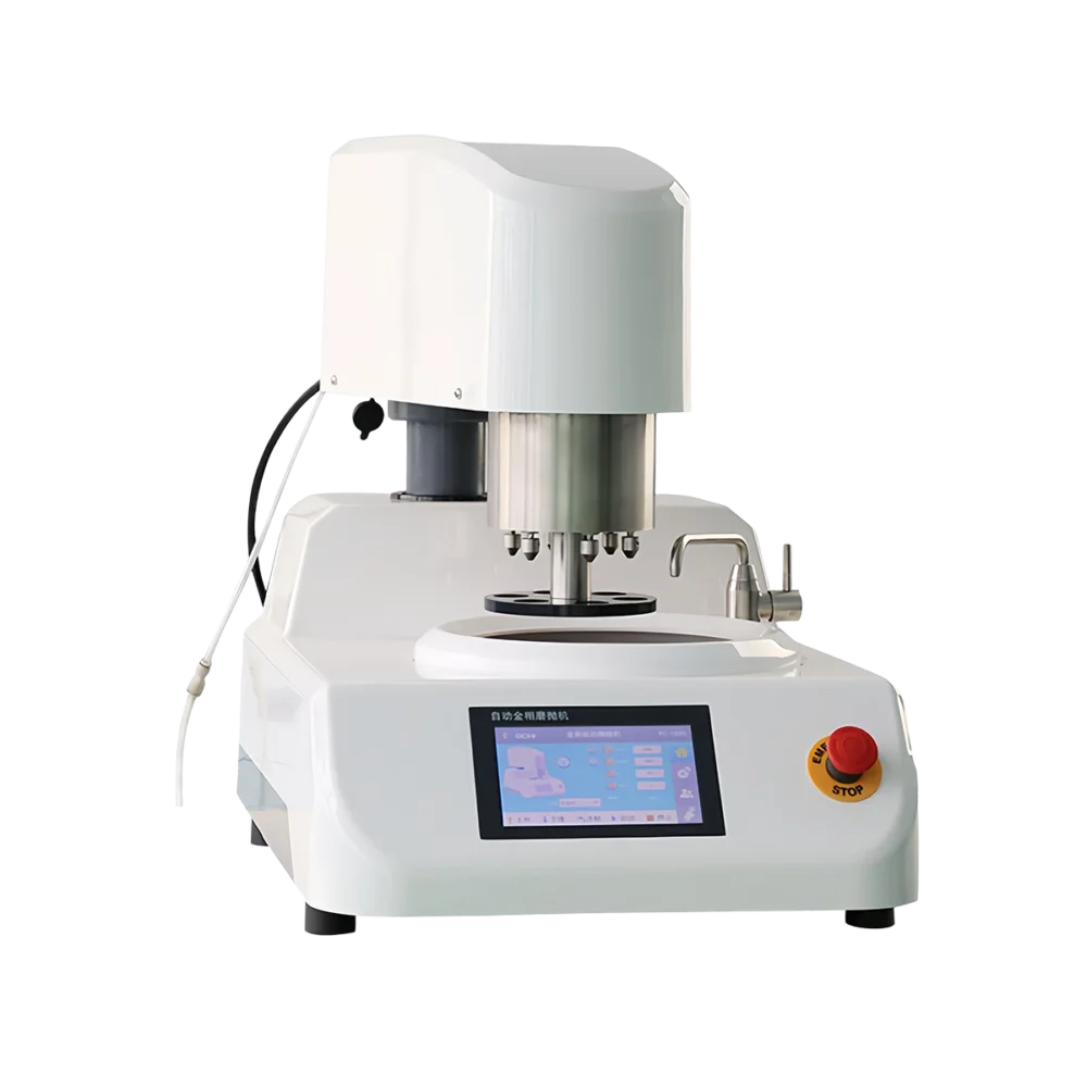
The appropriate metallographic grinder-polisher is the one that controls the variables your application requires and produces acceptable specimens with a manageable operating burden.
Manual vs. Semi-Automatic vs. Automatic Preparation
Compare functions rather than labels:
| Capability | Procurement question |
|---|---|
| Specimen handling | Which operations remain hand-held? |
| Force application | Is force applied per specimen or through a holder? |
| Method control | Can approved settings be stored and recalled? |
| Fluid delivery | Is delivery controlled and repeatable? |
| Cleaning | Which tasks remain manual? |
| Traceability | What settings and results can be recorded? |
Automation can improve consistency, but it does not correct an unsuitable abrasive sequence automatically.
Match Platen Size, Specimen Capacity and Holder Geometry
Specify actual mount sizes, sample count, component shapes, and target throughput.
A larger platen is not automatically a better investment. Confirm that the required holders, surfaces, and working area are compatible.
Compare Force Control, Speed Range, and Method Repeatability
Ask suppliers to demonstrate the operating conditions your method needs.
A wide published range does not prove control quality at the settings relevant to your specimens.
Single-Platen vs. Dual-Platen Machines
A dual-platen arrangement may simplify workflow or reduce surface changes. It does not inherently double accepted output.
Compare changeover, contamination control, available space, operator workload, and the preparation sequence.
Evaluate Dosing, Cleaning, Drainage, and Maintenance
Include daily practicalities:
-
Access for cleaning.
-
Slurry and debris accumulation.
-
Drainage.
-
Holder inspection.
-
Surface replacement.
-
Fluid-system maintenance.
-
Spare parts and service access.
What to Ask for in a Supplier Demonstration
Provide representative specimens, including the most difficult routine material.
Request:
-
Complete equipment and consumable identification.
-
Full parameter settings.
-
Ground and final-polished images.
-
Hands-on and elapsed times.
-
Material-removal or target-position checks.
-
Rework observations.
-
Required accessories and recurring consumables.
Use these trial results to compare metallographic grinding and polishing machines by specimen capacity, force application, method control, and operator workload. Select the configuration that meets your validated preparation requirements—not simply the model with the largest platen or widest speed range.
How to Validate a Grinding Method Before Routine Use
A method is not validated because one specimen looked good once.
Define Acceptance Criteria Around the Analysis Task
Specify the required plane, edge condition, artifact limits, and downstream analytical suitability.
Do not impose one universal surface-roughness value on unrelated materials and inspection tasks.
Check Flatness, Scratch Removal, Edge Integrity, and Artifacts
Use a structured inspection record. A single attractive image may miss a damaged edge or an unrepresentative region.
Verify the Final Polished Surface—not Just the Ground Surface
Some unresolved grinding problems become apparent only after further refinement or etching.
Validate the grinding stage within the complete preparation route. Residual deformation is particularly relevant to sensitive etching, high-magnification imaging, polarized-light examination, and EBSD.
Test Repeatability Across Operators, Runs and Consumable Life
Include different runs and relevant operators. Evaluate new, partially used, and near-replacement consumables.
This reveals whether the method depends on an unusually favorable surface condition.
Record the Variables Needed to Reproduce the Method
| Method-card field | Required detail |
|---|---|
| Specimen | Material, condition, geometry, target |
| Upstream preparation | Cutting and mounting method |
| Abrasive | Product, size, grading standard, backing |
| Holder | Type, specimen count, mounting arrangement |
| Force | Value, unit, and per-specimen or total definition |
| Motion | Platen/head speeds and directions |
| Fluid | Type and delivery conditions |
| Endpoint | Time, inspection condition, or removal limit |
| Result | Acceptance, artifacts, rework |
| Consumable condition | Usage, cleaning, conditioning, replacement |
Require Evidence Appropriate to the Claim
A supplier claiming reduced preparation time should show comparable specimens and equivalent acceptance criteria.
A supplier claiming better edge retention should show the relevant prepared interface.
A claim about lower consumable cost should include rejected specimens and rework—not only purchase price.
What Is the Real Cost per Acceptable Prepared Specimen?
The lowest-priced grinding paper is not necessarily the lowest-cost preparation method. The most automated machine is not necessarily the most economical configuration.
Compare Consumable Cost with Labor, Rework, and Lost Specimens
Include abrasive surfaces, fluids, cleaning, hands-on labor, regrinding, repolishing, equipment allocation, and specimen loss.
For an irreplaceable failure sample, loss of the target region may matter more than any small consumable saving.
Track First-Pass Yield and Hands-On Time
First-pass yield=Specimens accepted without rework/Specimens prepared×100%
Cost per accepted specimen=Total relevant cost/Accepted specimens
An Illustrative ROI Comparison
The following is a hypothetical planning example, not a measured customer result.
Assume two workflows each attempt 100 specimens:
| Input | Workflow A | Workflow B |
|---|---|---|
| Consumables | $120 | $180 |
| Hands-on labor at $30/hour | 10 hours / $300 | 6 hours / $180 |
| Allocated equipment and maintenance | $30 | $70 |
| Cost before rework | $450 | $430 |
| Specimens requiring rework | 15 | 5 |
| Rework cost at $8 each | $120 | $40 |
| Total cost, assuming all are recovered | $570 | $470 |
| Final accepted specimens | 100 | 100 |
| Cost per accepted specimen | $5.70 | $4.70 |
Under these assumptions, Workflow B reduces cost by $1 per accepted specimen. At 1,000 accepted specimens per month, that would represent $1,000 in monthly savings.
If adopting Workflow B required an additional $12,000 investment, the simple payback would be 12 months. This excludes financing, taxes, implementation, demand changes, and other costs. The result is valid only if the assumed labor, rework, and acceptance improvements are demonstrated.
Decide Whether the Bottleneck Is the Machine, Consumable, or Method
Before purchasing, determine whether the main constraint is:
-
Insufficient machine capacity.
-
An unsuitable abrasive system.
-
Excessive operator involvement.
-
Poor cleaning.
-
Incorrect mounting.
-
Severe incoming cutting damage.
-
An unvalidated sequence.
The correct investment may be a new machine, but it may also be a better consumable, holder, training program, or upstream process.
Metallographic Grinding FAQ
What Is the Purpose of Rough Grinding for Metallographic Examination?
Rough or plane grinding establishes the examination plane and removes initial damage. It should not introduce more damage than necessary.
What Is the Difference Between Coarse and Fine Grinding?
Coarse grinding prioritizes initial flattening and stock removal. Fine grinding removes preceding damage and prepares the surface for subsequent refinement. The boundary depends on the preparation system.
Which Grit Should You Start With?
Use the finest abrasive that can efficiently flatten the specimen and remove existing damage. Evaluate the incoming cut and material rather than choosing one grit for every specimen.
Is P600 the Same as 600 Grit?
No. FEPA P600 and ANSI/CAMI 600 have different approximate particle sizes. Record the grading system.
Can Metallographic Grinding Change Measured Hardness?
An unsuitable preparation process can alter the near-surface condition or compromise the surface used for indentation. That does not mean metallographic grinding is intended to soften or strengthen the material.
Does a Shiny Surface Mean Grinding Is Complete?
No. Appearance does not demonstrate flatness or complete damage removal.
When Should Grinding Paper or a Grinding Disc Be Replaced?
Replace or condition it according to supplier instructions and validated limits for removal rate, loading, damage, and surface quality.
Can One Grinding Method Be Used for Steel and Aluminum?
Possibly, but only if both results are validated. Different deformation behavior and phase structures may require different starting abrasives or process conditions.
Do Metallographic Grinding Machines Require Maintenance?
Yes. Follow the machine instructions for cleaning, holders, moving components, fluid systems, and drainage. Maintenance requirements should be included in purchasing comparisons.
When Is Automatic Preparation Worth the Investment?
When representative trials demonstrate a useful improvement in accepted output, repeatability, operator workload, or total cost under the laboratory’s actual sample volume.
Choose a Grinding Method Around Your Specimen and Inspection Requirement
A reliable grinding method answers four questions:
-
What damage must be removed?
-
What feature must be preserved?
-
Which abrasive and control system can achieve both consistently?
-
What evidence demonstrates acceptable quality and economic value?
Start there—not with the largest machine, the longest grit sequence, or the cheapest disc.
Request a Grinding Method and Equipment Recommendation
Struggling with persistent scratches, edge rounding, or inconsistent preparation time? Send us your specimen material, dimensions, mounting method, current grinding sequence, and target analysis. We can help evaluate suitable grinding surfaces, process controls, and equipment for your laboratory requirements.
Include your current parameter settings, consumable designations, specimen photographs, and daily preparation volume so the discussion can focus on your actual process.